Introduction
Drone is an Embedded Operating System for writing real-time applications in Rust. It aims to bring modern development approaches without compromising performance into the world of embedded programming.
Supported hardware
As of today, Drone can run on ARMv7-M, ARMv8-M, and RISC-V architectures. It is tested on Cortex®-M3, Cortex®-M4, Cortex®-M33, Nuclei Bumblebee cores, and STM32, NRF52, NRF91, GD32VF103 MCU series.
Other hardware support is likely to be added in the future. One restriction for adding a new architecture is that it must implement atomic CAS (compare-and-swap) operations, as Drone highly relies on good atomics support from hardware.
As of debug probes, Drone utilities provide native support for J-Link and Black Magic Probe, as well as generic interface to OpenOCD.
Design principles
-
Energy effective from the start. Drone encourages interrupt-driven execution model.
-
Hard Real-Time. Drone relies on atomic operations instead of using critical sections.
-
Fully preemptive multi-tasking with strict priorities. A higher priority task takes precedence with minimal latency.
-
Highly concurrent. Multi-tasking in Drone is very cheap, and Rust ensures it is also safe.
-
Message passing concurrency. Drone ships with synchronization primitives out of the box.
-
Single stack by default. Drone concurrency primitives are essentially stack-less state machines. But stackful tasks are still supported.
-
Dynamic memory enabled. Drone lets you use convenient data structures like mutable strings or vectors while still staying deterministic and code efficient.
Why use Drone?
-
Async/await by default. Drone provides all required run-time to use native async/await syntax and execute
Futures. -
Doesn't require
unsafecode. In spite of the fact that Drone core inevitably relies onunsafecode, Drone applications can fully rely on the safe abstractions provided by Drone. -
Modern tooling. Apart from standard Rust tools like
cargopackage manager,rustfmtcode formatter,clippycode linter, Drone providesdronecommand-line utility which can generate a new Drone project for your hardware, or manage your debug probe. -
Primary stack is stack-overflow protected regardless of MMU/MPU presence. But secondary stackful tasks require MMU/MPU to ensure the safety.
-
Debug communication channels. Rust's
print!,eprint!and similar macros are mapped to Cortex-M's SWO channels 0 and 1 out of the box. Debug messages incur no overhead when no debug probe is connected. -
Drone.tomlconfiguration file, which saves you from manually writing linker scripts. -
Rich and safe zero-cost abstractions for memory-mapped registers. Drone automatically generates register bindings from vendor-provided SVD files. It also provides a way to write code generic over similar peripherals.
What Drone doesn't
-
Drone doesn't support loading dynamic applications. It is a library OS and is linked statically with its application.
-
Drone doesn't implement time-slicing. It has a different execution model, but optional time-slicing may be added in the future.
Getting Started
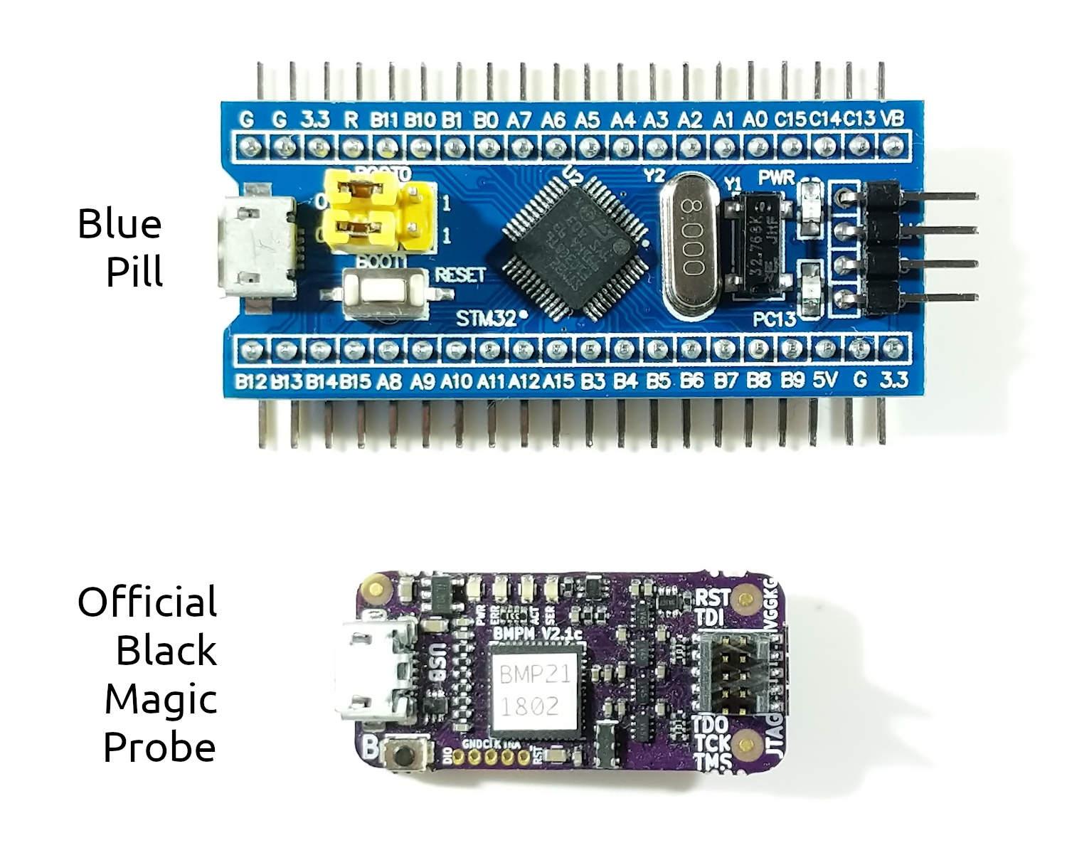
Unlike many other programming fields, software development for embedded systems requires special hardware. Bare minimum is a target device, for which the software is developed, and a debug probe that is responsible for programming and debugging the device. Often for a particular microcontroller unit (MCU), the vendor offers a development board, which incorporates an MCU, a debug probe, and some peripherals. But when the development reaches a printed circuit board (PCB) prototyping stage, an external probe is desirable. There are various debug probes in the market. A Chinese clone can cost a couple of dollars, while original probes often cost hundreds. But there is one unique option that is supported by Drone out-of-the-box - Black Magic Probe.
Black Magic Probe, or BMP, is an open-source tool, like Rust or Drone, which is invaluable when it comes to troubleshooting. Currently it supports Cortex-M and Cortex-A targets. BMP implements the GDB protocol directly, which is nice, because there is no need for intermediate software like OpenOCD. Also it embeds a USB-to-UART converter. The official hardware is sold around $60 and is quite good. But the firmware supports other hardware options. The most affordable of which is the Blue Pill.
Blue Pill is an ultra-popular and cheap development board for STM32F103C8T6 microcontroller. It can be bought for around $1.50 from AliExpress and also can be programmed with Drone. It has 32-bit Cortex-M3 core running at 72 Mhz max, 20 Kb of RAM, and 128 Kb of flash memory. This is good for many applications and is enough to get started with Drone. So the most affordable start would be with two Blue Pill boards, one as a debug probe and the other as the host for Drone projects.
But there is another tool needed to flash the BMP firmware to a Blue Pill - a USB-to-UART adapter. Out of the box a Blue Pill is flashed with a factory boot loader, which allows programming its flash memory through UART. The cheapest adapter would be enough for this. CH340G can be bought for around $0.50 from AliExpress. It will not be needed after initial bootstrap of BMP, because it has its own USB-to-UART. Though it is convenient to have a spare adapter, as sometimes there can be multiple UARTs involved.
Hardware
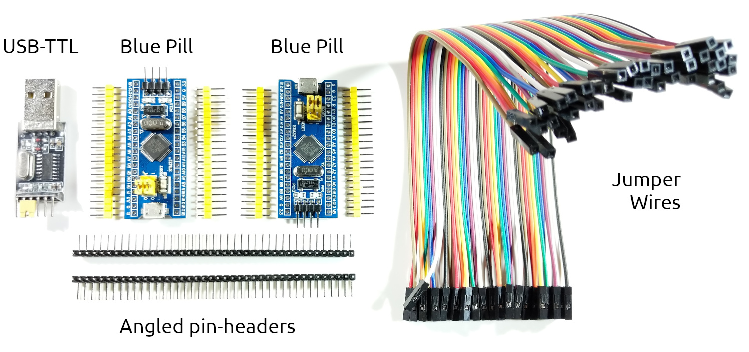
To make a start with Drone the most affordable, the following reference hardware was selected for this book:
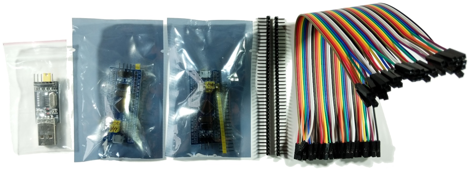
- 2× STM32F103C8T6 development boards (Blue Pills)
- CH340G USB-TTL converter
- Female-to-female jumper wires
And optionally:
- 2× Angled 40-pins 2.54 mm header - Blue Pills already come with straight pin headers
Usually Blue Pills come with not soldered pin-headers, except the SWD header. If you don't want to solder, you can twist the wires like this:
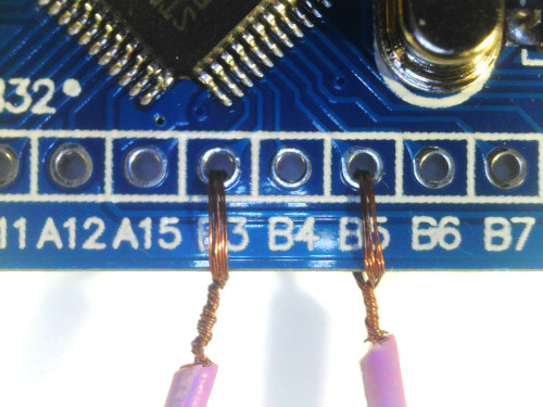
Please be aware that the above method can lead to signal integrity issues or shorts. Therefore proper soldering is recommended. Here are the Blue Pills soldered with the angled pin-headers:
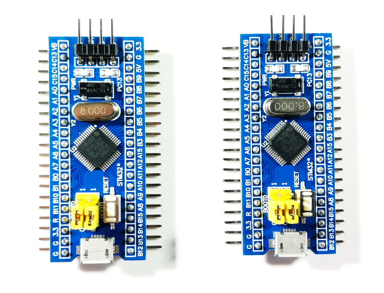
In the next chapter we will show how to convert one of the Blue Pills to a Black Magic Proble.
Black Magic Probe from a Blue Pill
This chapter describes the process of making a Black Magic Probe from a Blue Pill board. The steps were tested on Ubuntu 18.04.3 LTS and Arch Linux 5.3.7.
Preparation
The process requires the following packages to be installed:
$ sudo apt install build-essential \
                   curl \
                   dfu-util \
                   gcc-arm-none-eabi \
                   gdb-multiarch \
                   git \
                   python \
                   python-pip
or on Arch Linux:
$ sudo pacman -S curl \
                 dfu-util \
                 git \
                 python \
                 python-pip
$ yaourt -S arm-none-eabi-gcc \
            gdb-multiarch
It is convenient to join the dialout group. This way you will not need
super-user privileges to work with BMP and USB-to-UART adapter:
$ sudo adduser $(id -un) dialout
or the uucp group on Arch Linux:
$ sudo gpasswd -a $(id -un) uucp
In order for the group change to take effect, you will need to re-login.
Get the stm32loader script and install its python dependencies:
$ git clone https://github.com/jsnyder/stm32loader
$ pip install pyserial
Get the BMP firmware:
$ git clone https://github.com/blacksphere/blackmagic
$ cd blackmagic
$ git submodule update --init --recursive
BMP repository provides udev rules for the probe. The rules instruct udev to
symlink the GDB endpoint to /dev/ttyBmpGdb and the UART to
/dev/ttyBmpTarg. Also they allow to upgrade BMP firmware without super-user
permissions.
$ sudo cp driver/99-blackmagic.rules /etc/udev/rules.d/
$ sudo udevadm control --reload-rules
Building
Correct probe host should be selected. In our case it's swlink.
$ make PROBE_HOST=swlink
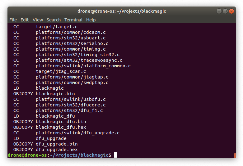
This will produce two binaries we are interested in: src/blackmagic_dfu.bin
and src/blackmagic.bin. The first is a bootloader, which will be flashed with
the USB-to-UART adapter. And the second is the actual firmware, which will be
loaded through USB with help of the bootloader.
Flashing Bootloader
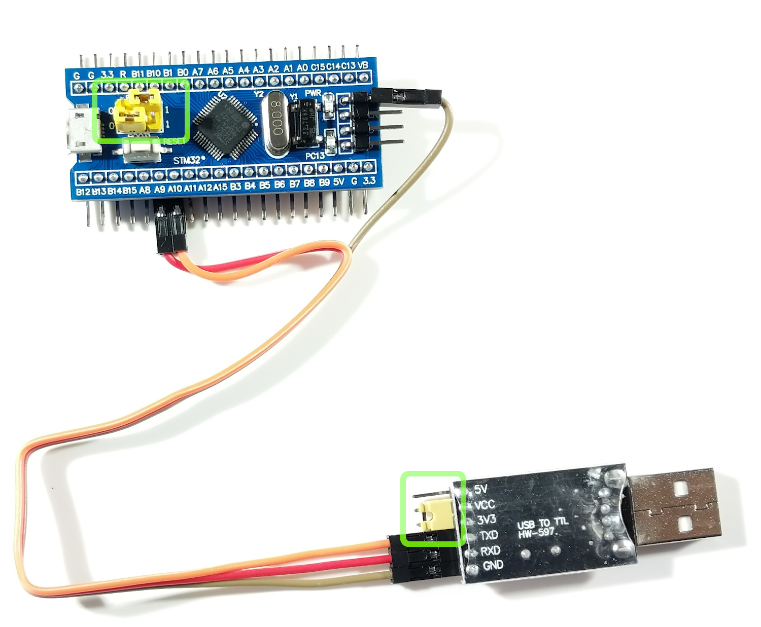
-
Connect the USB-to-UART adapter with the Blue Pill according to this table:
USB-to-UART Blue Pill GND GND RXD A9 TXD A10 Warning: Don't connect any power source now. We will power up the board through USB at the step 5. Using USB together with 5V or 3.3 pins can damage your board.
-
Set the jumper on the USB-to-UART adapter to the position where VCC and 3V3 are shorted. This will set the adapter's output voltage to 3.3 v. Although it is not strictly needed, because A9 and A10 pins are five-volt-tolerant.
-
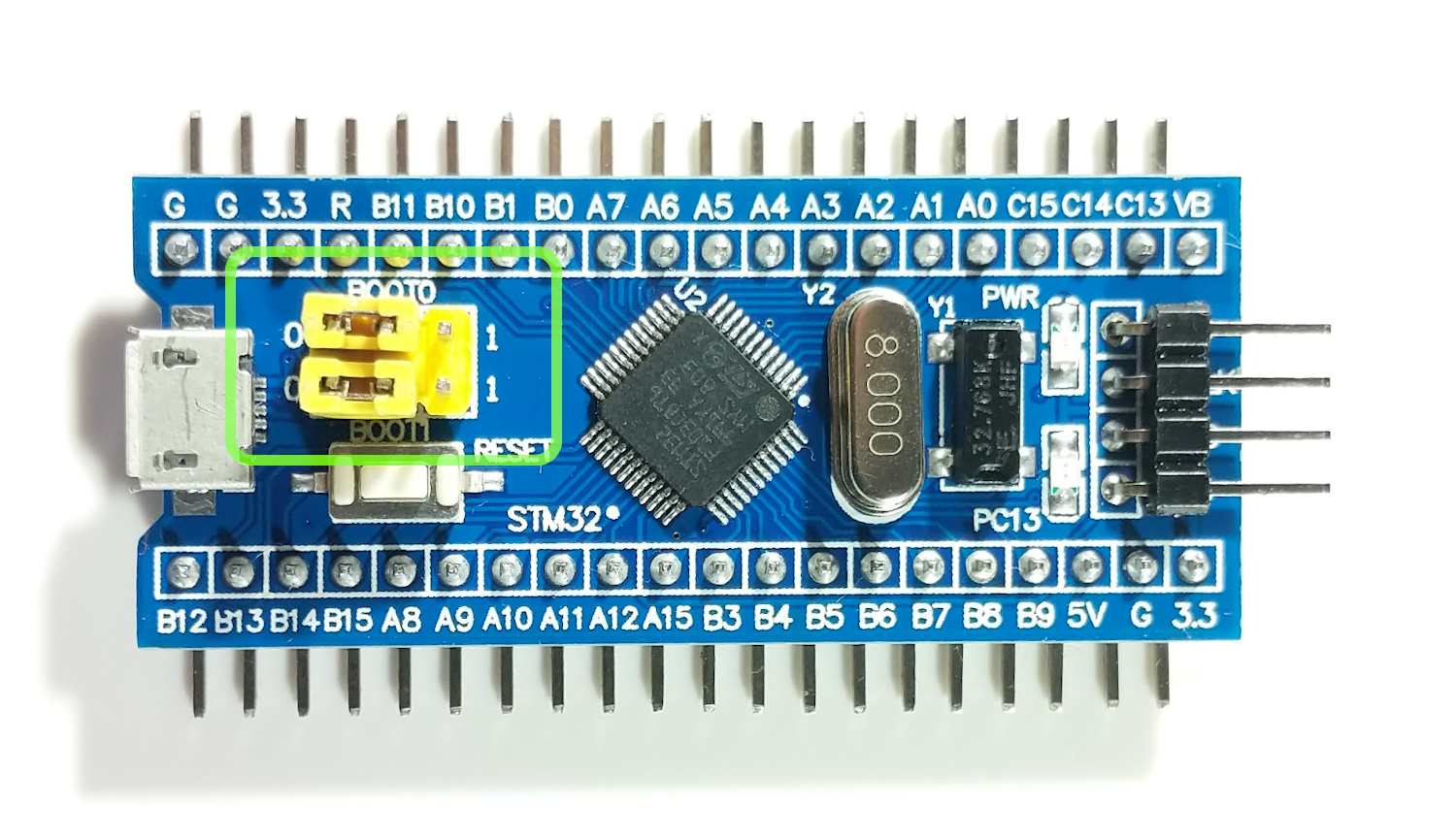
Set BOOT0 jumper on the Blue Pill to 1 to boot into the factory programmed bootloader. The bootloader is responsible for programming the board through UART.
-
Before connecting the USB-to-UART adapter to your PC, open the system journal:
$ journalctl -fConnect the USB-to-UART adapter and notice the name it is assigned:
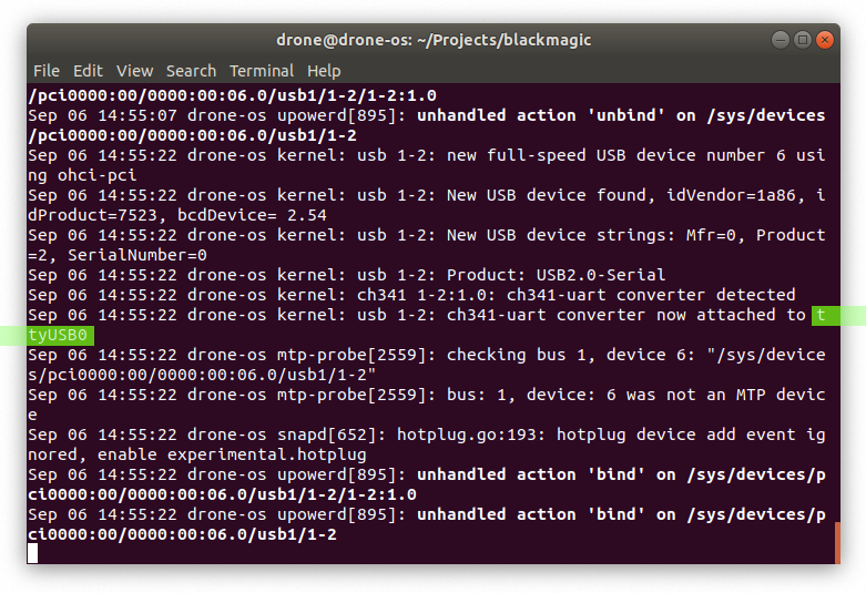
-
Connect a USB-cable to the Blue Pill and start the flashing process. Replace
/dev/ttyUSB0with your value from the previous step. If the process is not starting, press the reset button on the Blue Pill.$ ../stm32loader/stm32loader.py -p /dev/ttyUSB0 -e -w -v src/blackmagic_dfu.bin
- Set BOOT0 jumper on the Blue Pill back to 0.
Flashing Firmware
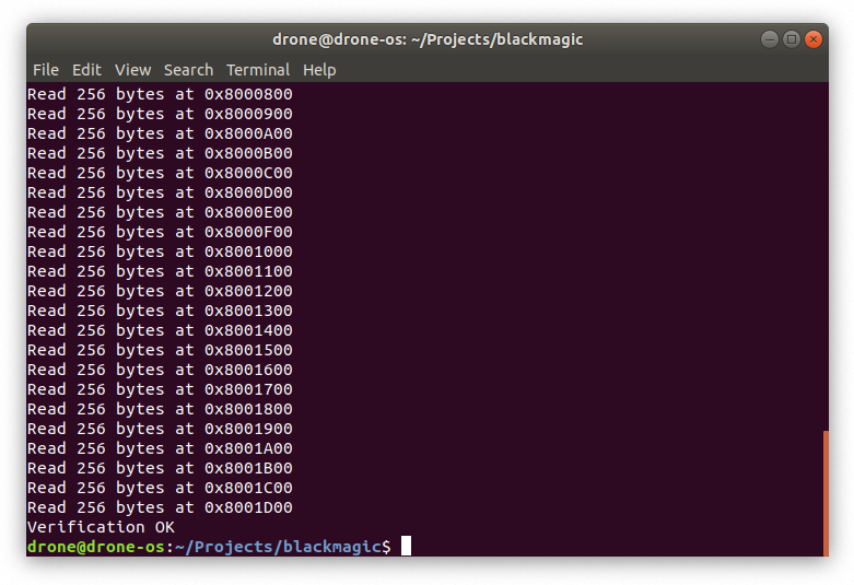
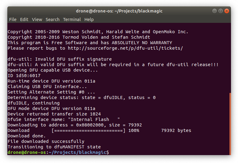
Now you can disconnect the USB-to-UART adapter from the Blue Pill and your PC. The firmware will be flashed through USB port:
$ dfu-util -d 1d50:6018,:6017 -s 0x08002000:leave -D src/blackmagic.bin
Now we will check that it works. Reconnect the Blue Pill and open a GDB session:
$ gdb-multiarch
At the GDB prompt enter the following commands:
target extended-remote /dev/ttyBmpGdb
monitor version
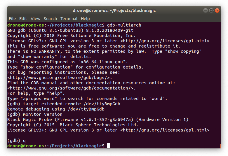
If your output is similar to the output above, congratulations! Now your Blue
Pill is a Black Magic Probe! Next time you need to upgrade the firmware you only
need to repeat the dfu-util command above.
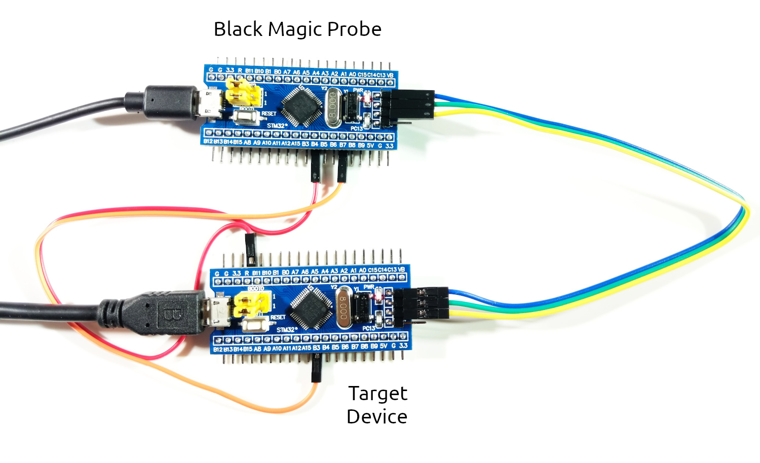
Wiring
Here is a general pin-out description and an example connection with a Blue Pill:
| Black Magic Probe | Function | Blue Pill Target |
|---|---|---|
| GND | GND | GND |
| SWCLK | JTCK/SWCLK | SWCLK |
| SWIO | JTMS/SWDIO | SWIO |
| A15 | JTDI | |
| B3 | JTDO | |
| B4 | JNTRST | R |
| B6 | UART1 TX | |
| B7 | UART1 RX | B3 |
| A3 | UART2 RX (TRACESWO) |
Comparison with Official BMP
There are a few advantages of the official BMP:
- Has a Cortex Debug connector
- Can power the target
- Can sense the target's voltage
- Has more LEDs
- Has more robust circuitry
These advantages are not critical, however by buying the official hardware you are supporting the BMP project.
Hello, world!
In the previous chapter we created a debug probe from a Blue Pill, and attached it to another Blue Pill board. In this chapter we will run our first Drone program on the microcontroller.
Rust
If you haven't installed Rust yet, follow the instructions from rustup.rs. Drone is currently available only for Nightly channel of Rust. You need to install it first:
$ rustup toolchain install nightly \
      -c rust-src -c rustfmt -c clippy -c llvm-tools-preview \
      -t thumbv7m-none-eabi
Not all nightly releases have all components available. The above command will walk backwards in time to find the most recent release with all needed components.
just command
In embedded development often there are various project-specific tasks that are
needed to run from time to time. Therefore we encourage using an excellent Rust
crate just:
$ cargo +stable install just
Just is a command runner inspired by make. Whenever you see a project with
Justfile at the root, run just --list to see all available
commands. Furthermore drone new command will generate a Justfile for you. It
is advisable to put alias j="just" to your shell config, so you could just
type j instead of just.
drone command
The Drone OS project consists of many Rust crates. However there is a single
entry point for it - the drone command-line utility:
$ cargo +nightly install drone
For now you should have all prerequisites and could follow to the next step - generating your first Drone crate.
New project
Let's tell drone to generate a new Drone crate for us. We have to specify the
target MCU family, which is stm32f103 for Blue Pill, the flash memory size,
the RAM size, and the project name.
$ drone new --device stm32f103 --flash-size 128K --ram-size 20K hello-world
$ cd hello-world
The first thing to do inside the project is to install dependencies:
$ just deps
You should also run this task after each Rust update.
Now we assume you have the Blue Pills connected as follows (as described in the previous chapter):
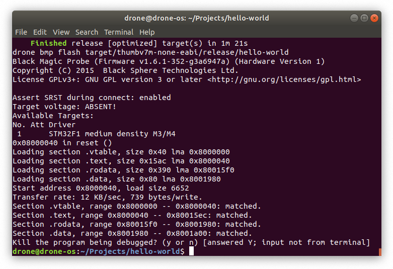
Let's flash our newly created project to the target Blue Pill. If it has to be built first, it could take a while:
$ just flash
A successful result looks like this:
And finally, check the SWO output from the device.
$ just log
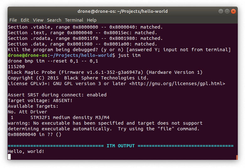
If you see an output like above, congratulations! You have successfully set up an environment for developing Drone projects.
Blink an LED
In this section we will write an application that will raise the system clock frequency to 72 MHz and blink the on-board LED connected to the PC13 pin. The application will involve using multiple threads, futures, streams, memory-mapped registers, and peripherals.
The full code for this example can be found at Github.
Generate a project
To begin with, let's generate a new Drone project for a Blue Pill board:
$ drone new \
        --toolchain nightly-2020-04-30 \ # we need to pick a fresh nightly with
                                       \ # all required rustup components
        --device stm32f103 \ # microcontroller identifier
        --flash-size 128K \ # flash memory size in bytes
        --ram-size 20K \ # RAM size in bytes
        bluepill-blink # project name
$ cd bluepill-blink
$ just deps
To briefly test the newly generated application, connect a Black Magic Probe to your PC, and a Blue Pill board to the BMP as in Hello, world! chapter. Flash the firmware and check the SWO output:
$ just flash
$ just log
If you can see a "Hello, world!" message, follow to the next chapter.
Run at Full Speed
According to the datasheet, STM32F103 MCU can run at the maximum frequency of 72 MHz. But by default it runs at only 8 MHz. To achieve the full potential of the chip, the system frequency should be raised in the run-time.
There are three options for the system clock source:
-
HSI (High Speed Internal) - an RC oscillator running at constant 8 MHz and sitting inside the MCU chip. It is the default source for the system clock selected at the start-up.
-
HSE (High Speed External) - an optional external resonator component in the range from 4 to 16 MHz. A Blue Pill board has a 8 MHz crystal connected to the MCU (the component in a metal case right beside the MCU marked as Y2.)
-
PLL (Phase-Locked Loop) - a peripheral inside the MCU that can be used as a multiplier for HSI or HSE. The maximum multiplier for HSI is 8, which can give us 64 MHz, and for HSE - 16, which can theoretically result in 128 MHz, but the output frequency of PLL shouldn't exceed 72 MHz.
Given the above, in order to achieve 72 MHz, we should take the following steps:
- Start the HSE oscillator and wait for it to stabilize.
- Start the PLL with the HSE input and the multiplier of 9. Wait for it to stabilize.
- Select the PLL as the source for the system clock.
For a start, let's create a module for our project-level constants. Create a new
file at src/consts.rs with the following content:
#![allow(unused)]
fn main() {
//! Project constants.

/// HSE crystal frequency.
pub const HSE_FREQ: u32 = 8_000_000;

/// PLL multiplication factor.
pub const PLL_MULT: u32 = 9;

/// System clock frequency.
pub const SYS_CLK: u32 = HSE_FREQ * PLL_MULT;
}
And register the module in the src/lib.rs:
#![allow(unused)]
fn main() {
pub mod consts;
}
When the application will need to wait for HSE and PLL clocks stabilization, we don't want it to be constantly checking the flags wasting CPU cycles and energy, but rather to subscribe for an interrupt and sleep until it is triggered. We will use the RCC interrupt for this purpose:
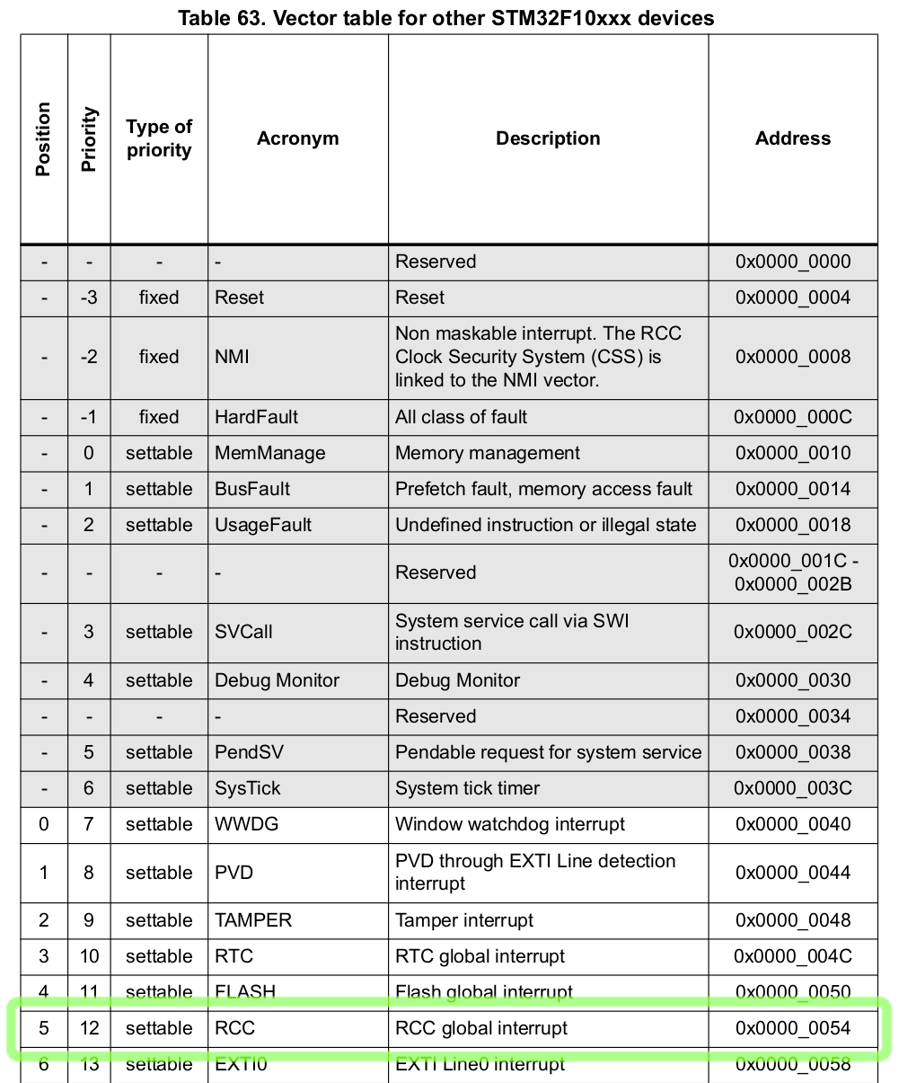
From the table above, which can be found in the Reference Manual, we only need
the position of the RCC interrupt. Let's put this interrupt to the application
Vector Table. For this you need to edit thr::nvic! macro in src/thr.rs. By
default it looks like this:
#![allow(unused)]
fn main() {
thr::nvic! {
    // ... The header is skipped ...

    threads => {
        exceptions => {
            /// All classes of faults.
            pub hard_fault;
        };
    };
}
}
There is only a HardFault handler defined. Note that according the above table, HardFault doesn't have a position number, therefore it is referred only by its name. We need to add a new interrupt handler at the position of 5:
#![allow(unused)]
fn main() {
thr::nvic! {
    // ... The header is skipped ...

    threads => {
        exceptions => {
            /// All classes of faults.
            pub hard_fault;
        };
        interrupts => {
            /// RCC global interrupt.
            5: pub rcc;
        };
    };
}
}
Since the new handler has a numeric position, the name can be arbitrary.
Let's open the root task handler at src/tasks/root.rs. By default it looks
like this:
#![allow(unused)]
fn main() {
//! The root task.

use crate::{thr, thr::ThrsInit, Regs};
use drone_cortexm::{reg::prelude::*, thr::prelude::*};

/// The root task handler.
#[inline(never)]
pub fn handler(reg: Regs, thr_init: ThrsInit) {
    let thr = thr::init(thr_init);

    thr.hard_fault.add_once(|| panic!("Hard Fault"));

    println!("Hello, world!");

    // Enter a sleep state on ISR exit.
    reg.scb_scr.sleeponexit.set_bit();
}
}
In Drone OS the very first task with the lowest priority named root. Its
function handler is called by the program entry point at
src/bin/bluepill-blink.rs, after finishing unsafe initialization routines. The
root handler receives two arguments of types Regs and ThrsInit. Both are
zero-sized types implementing Token trait, which permits existence of only one
instance at a time. Instantiating a Token type is unsafe, that is why it is
done inside the unsafe entry point at src/bin/bluepill-blink.rs.
The reg argument is a set of tokens for all available memory-mapped
registers. It is supposed to be destructured into individual register tokens or
register field tokens within the root handler.
The second thr_init argument's purpose is to pass it to thr::init
function. The function runs an initialization routine for threading system and
returns an instance of Thrs type. Thrs is also a zero-sized type similar to
Regs, but for thread tokens.
The root handler adds a one-shot fiber to the HardFault thread. The fiber body
is just a call to the panic! macro. Drone handles panics by writing the panic
message to the log output at port #1, issuing a self-reset request, and blocking
until it's executed.
Let's add a new async function that will be responsible for raising the system
clock frequency to 72 MHz. It will need some registers from RCC and FLASH
peripherals, as well as the RCC thread token.
#![allow(unused)]
fn main() {
//! The root task.

use crate::{
    consts::{PLL_MULT, SYS_CLK},
    thr,
    thr::ThrsInit,
    Regs,
};
use drone_core::log;
use drone_cortexm::{fib, reg::prelude::*, swo, thr::prelude::*};
use drone_stm32_map::reg;

/// The root task handler.
#[inline(never)]
pub fn handler(reg: Regs, thr_init: ThrsInit) {
    let thr = thr::init(thr_init);

    thr.hard_fault.add_once(|| panic!("Hard Fault"));

    raise_system_frequency(
        reg.flash_acr,
        reg.rcc_cfgr,
        reg.rcc_cir,
        reg.rcc_cr,
        thr.rcc,
    )
    .root_wait();

    println!("Hello, world!");

    // Enter a sleep state on ISR exit.
    reg.scb_scr.sleeponexit.set_bit();
}

async fn raise_system_frequency(
    flash_acr: reg::flash::Acr<Srt>,
    rcc_cfgr: reg::rcc::Cfgr<Srt>,
    rcc_cir: reg::rcc::Cir<Srt>,
    rcc_cr: reg::rcc::Cr<Srt>,
    thr_rcc: thr::Rcc,
) {
    // TODO raise the frequency to 72 MHz
}
}
An async function is a syntax sugar for a function returning a custom type
implementing Future trait. We execute the returned future using the
.root_wait() method. The root_wait method is supposed to be used inside a
thread with the lowest priority, e.g. in the root task context. Otherwise the
threads that are currently preempted may be stalled. Another option for
executing futures is to use exec or add_exec methods on thread tokens.
It's good to check that the program still works:
$ just flash
$ just log
Let's start filling out the raise_system_frequency function. First, we need to
enable the RCC interrupt in NVIC (Nested Vectored Interrupt Controller), and
allow the RCC peripheral to trigger the interrupt when HSE or PLL is stabilized:
#![allow(unused)]
fn main() {
    thr_rcc.enable_int();
    rcc_cir.modify(|r| r.set_hserdyie().set_pllrdyie());
}
Then we're enabling the HSE clock and waiting until it's stabilized:
#![allow(unused)]
fn main() {
    // We need to move ownership of `hserdyc` and `hserdyf` into the fiber.
    let reg::rcc::Cir {
        hserdyc, hserdyf, ..
    } = rcc_cir;
    // Attach a listener that will notify us when RCC_CIR_HSERDYF is asserted.
    let hserdy = thr_rcc.add_future(fib::new_fn(move || {
        if hserdyf.read_bit() {
            hserdyc.set_bit();
            fib::Complete(())
        } else {
            fib::Yielded(())
        }
    }));
    // Enable the HSE clock.
    rcc_cr.modify(|r| r.set_hseon());
    // Sleep until RCC_CIR_HSERDYF is asserted.
    hserdy.await;
}
And similarly enable the PLL:
#![allow(unused)]
fn main() {
    // We need to move ownership of `pllrdyc` and `pllrdyf` into the fiber.
    let reg::rcc::Cir {
        pllrdyc, pllrdyf, ..
    } = rcc_cir;
    // Attach a listener that will notify us when RCC_CIR_PLLRDYF is asserted.
    let pllrdy = thr_rcc.add_future(fib::new_fn(move || {
        if pllrdyf.read_bit() {
            pllrdyc.set_bit();
            fib::Complete(())
        } else {
            fib::Yielded(())
        }
    }));
    rcc_cfgr.modify(|r| {
        r.set_pllsrc() // HSE oscillator clock selected as PLL input clock
            .write_pllmul(PLL_MULT - 2) // output frequency = input clock × PLL_MULT
    });
    // Enable the PLL.
    rcc_cr.modify(|r| r.set_pllon());
    // Sleep until RCC_CIR_PLLRDYF is asserted.
    pllrdy.await;
}
The flash memory settings should be tweaked because of increased frequency:
#![allow(unused)]
fn main() {
    // Two wait states, if 48 MHz < SYS_CLK <= 72 Mhz.
    flash_acr.modify(|r| r.write_latency(2));
}
Before increasing the frequency, we should wait until the currently ongoing SWO
transmission is finished if any. And also update the SWO prescaler to maintain
the fixed baud-rate defined at the project's Drone.toml. Note that if a debug
probe is not connected, this will be a no-op, thus it's safe to keep this in the
release binary.
#![allow(unused)]
fn main() {
    swo::flush();
    swo::update_prescaler(SYS_CLK / log::baud_rate!() - 1);
}
And finally switch the source for the system clock to PLL:
#![allow(unused)]
fn main() {
    rcc_cfgr.modify(|r| r.write_sw(0b10)); // PLL selected as system clock
}
Here is the final listing of the raise_system_frequency function:
#![allow(unused)]
fn main() {
async fn raise_system_frequency(
    flash_acr: reg::flash::Acr<Srt>,
    rcc_cfgr: reg::rcc::Cfgr<Srt>,
    rcc_cir: reg::rcc::Cir<Srt>,
    rcc_cr: reg::rcc::Cr<Srt>,
    thr_rcc: thr::Rcc,
) {
    thr_rcc.enable_int();
    rcc_cir.modify(|r| r.set_hserdyie().set_pllrdyie());

    // We need to move ownership of `hserdyc` and `hserdyf` into the fiber.
    let reg::rcc::Cir {
        hserdyc, hserdyf, ..
    } = rcc_cir;
    // Attach a listener that will notify us when RCC_CIR_HSERDYF is asserted.
    let hserdy = thr_rcc.add_future(fib::new_fn(move || {
        if hserdyf.read_bit() {
            hserdyc.set_bit();
            fib::Complete(())
        } else {
            fib::Yielded(())
        }
    }));
    // Enable the HSE clock.
    rcc_cr.modify(|r| r.set_hseon());
    // Sleep until RCC_CIR_HSERDYF is asserted.
    hserdy.await;

    // We need to move ownership of `pllrdyc` and `pllrdyf` into the fiber.
    let reg::rcc::Cir {
        pllrdyc, pllrdyf, ..
    } = rcc_cir;
    // Attach a listener that will notify us when RCC_CIR_PLLRDYF is asserted.
    let pllrdy = thr_rcc.add_future(fib::new_fn(move || {
        if pllrdyf.read_bit() {
            pllrdyc.set_bit();
            fib::Complete(())
        } else {
            fib::Yielded(())
        }
    }));
    rcc_cfgr.modify(|r| {
        r.set_pllsrc() // HSE oscillator clock selected as PLL input clock
            .write_pllmul(PLL_MULT - 2) // output frequency = input clock × PLL_MULT
    });
    // Enable the PLL.
    rcc_cr.modify(|r| r.set_pllon());
    // Sleep until RCC_CIR_PLLRDYF is asserted.
    pllrdy.await;

    // Two wait states, if 48 MHz < SYS_CLK <= 72 Mhz.
    flash_acr.modify(|r| r.write_latency(2));

    swo::flush();
    swo::update_prescaler(SYS_CLK / log::baud_rate!() - 1);

    rcc_cfgr.modify(|r| r.write_sw(0b10)); // PLL selected as system clock
}
}
Work with a Timer
In this chapter we will work with a timer peripheral to timely assert and de-assert the PC13 pin, which is connected to the green LED on the Blue Pill board. The STM32F103 MCU possesses 7 timers of 4 different kinds. We will use the SysTick timer, which is present in all Cortex-M MCUs.
Drone already has a universal interface for timer peripherals in a form of
drone_cortexm::drv::timer::Timer trait, as well as the SysTick driver
implementation at drone_cortexm::drv::sys_tick::SysTick. However in this
walk-through we will use interrupts and memory-mapped registers directly.
Firstly, we need to allocate an interrupt used by the timer peripheral. Let's refer to the Reference Manual:
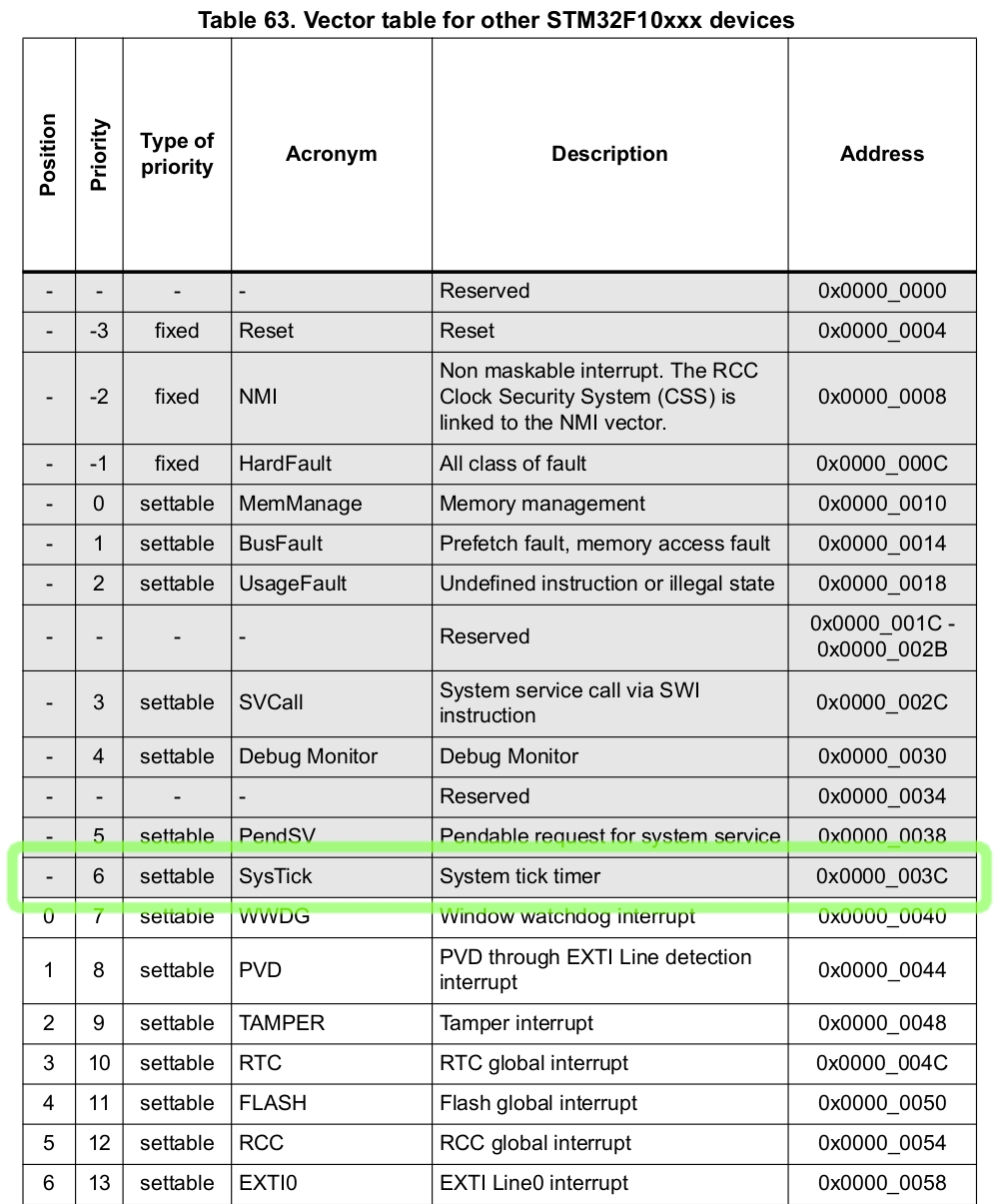
Unlike the RCC interrupt from the previous chapter, the SysTick doesn't have a position value. This means that we need to declare it using a precise name and before all the positional interrupts:
#![allow(unused)]
fn main() {
thr::nvic! {
    // ... The header is skipped ...

    threads => {
        exceptions => {
            /// All classes of faults.
            pub hard_fault;
            /// System tick timer.
            pub sys_tick;
        };
        interrupts => {
            /// RCC global interrupt.
            5: pub rcc;
        };
    };
}
}
According to the Reference Manual, the frequency of the SysTick clock is the
system clock divided by 8. Let's add this to our constants module
src/consts.rs:
#![allow(unused)]
fn main() {
/// SysTick clock frequency.
pub const SYS_TICK_FREQ: u32 = SYS_CLK / 8;
}
Let's update our root handler:
#![allow(unused)]
fn main() {
//! The root task.

use crate::{
    consts::{PLL_MULT, SYS_CLK, SYS_TICK_FREQ},
    thr,
    thr::ThrsInit,
    Regs,
};
use drone_core::log;
use drone_cortexm::{fib, reg::prelude::*, swo, thr::prelude::*};
use drone_stm32_map::{
    periph::{
        gpio::{periph_gpio_c, GpioC, GpioPortPeriph},
        sys_tick::{periph_sys_tick, SysTickPeriph},
    },
    reg,
};
use futures::prelude::*;

/// An error returned when a receiver has missed too many ticks.
#[derive(Debug)]
pub struct TickOverflow;

/// The root task handler.
#[inline(never)]
pub fn handler(reg: Regs, thr_init: ThrsInit) {
    let thr = thr::init(thr_init);
    let gpio_c = periph_gpio_c!(reg);
    let sys_tick = periph_sys_tick!(reg);

    thr.hard_fault.add_once(|| panic!("Hard Fault"));

    raise_system_frequency(
        reg.flash_acr,
        reg.rcc_cfgr,
        reg.rcc_cir,
        reg.rcc_cr,
        thr.rcc,
    )
    .root_wait();

    beacon(gpio_c, sys_tick, thr.sys_tick)
        .root_wait()
        .expect("beacon fail");

    // Enter a sleep state on ISR exit.
    reg.scb_scr.sleeponexit.set_bit();
}

// We leave this function unchanged.
async fn raise_system_frequency(...) {...}

async fn beacon(
    gpio_c: GpioPortPeriph<GpioC>,
    sys_tick: SysTickPeriph,
    thr_sys_tick: thr::SysTick,
) -> Result<(), TickOverflow> {
    Ok(())
}
}
We added an error type TickOverflow, which we discuss later:
#![allow(unused)]
fn main() {
#[derive(Debug)]
pub struct TickOverflow;
}
At the beginning of the root handler we added calls to two periph_*!
macros. These macros take parts of reg structure and move them into separate
gpio_c and sys_tick structures. The macros do nothing at the run-time,
because reg, gpio_c, and sys_tick are zero sized types, but they inform
the type system of moved ownership.
#![allow(unused)]
fn main() {
    let gpio_c = periph_gpio_c!(reg);
    let sys_tick = periph_sys_tick!(reg);
}
Those structures hold all registers associated with the corresponding
peripherals. We pass those peripheral structures to a new async function named
beacon. This time the function returns a Result type, and we handle it with
a panic:
#![allow(unused)]
fn main() {
    beacon(gpio_c, sys_tick, thr.sys_tick)
        .root_wait()
        .expect("beacon fail");
}
Let's start filling out the beacon function. We configure the SysTick timer
peripheral to trigger the SysTick interrupt each second:
#![allow(unused)]
fn main() {
    // Attach a listener that will notify us on each interrupt trigger.
    let mut tick_stream = thr_sys_tick.add_pulse_try_stream(
        // This closure will be called when a receiver no longer can store the
        // number of ticks since the last stream poll. If this happens, a
        // `TickOverflow` error will be sent over the stream as is final value.
        || Err(TickOverflow),
        // A fiber that will be called on each interrupt trigger. It sends a
        // single tick over the stream.
        fib::new_fn(|| fib::Yielded(Some(1))),
    );
    // Clear the current value of the timer.
    sys_tick.stk_val.store(|r| r.write_current(0));
    // Set the value to load into the `stk_val` register when the counter
    // reaches 0. We set it to the count of SysTick clocks per second, so the
    // reload will be triggered at each second.
    sys_tick.stk_load.store(|r| r.write_reload(SYS_TICK_FREQ));
    sys_tick.stk_ctrl.store(|r| {
        r.set_tickint() // Counting down to 0 triggers the SysTick interrupt
            .set_enable() // Start the counter
    });
}
Now the tick_stream variable holds an instance of a Stream type. We await
for each item of the stream until it ends. The tick variable is a number of
pulses (in our case seconds) passed since the last stream poll. If the thread is
not heavily interrupted, normally we expect it to be just 1.
#![allow(unused)]
fn main() {
    while let Some(tick) = tick_stream.next().await {
        for _ in 0..tick?.get() {
            println!("sec");
        }
    }
}
Let's flash this program and view the SWO output:
$ just flash
$ just log
You should see the following output. A "sec" line will be printed infinitely each second.
================================== LOG OUTPUT ==================================
sec
sec
sec
sec
sec
Now it's time to use the GPIO peripheral, to drive the green LED on our Blue Pill.
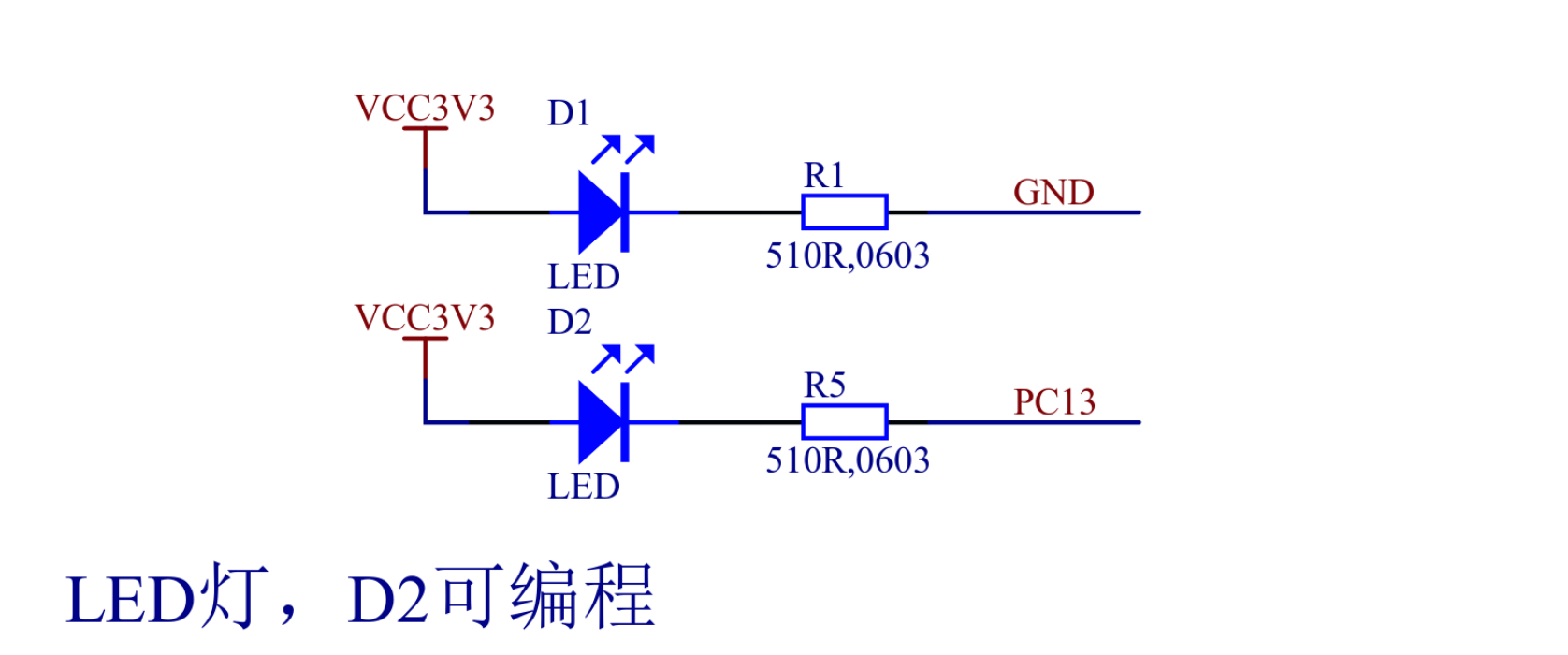
According to the Blue Pill schematic above, the current is flowing through D2
when PC13 line is low (shorted to GND), and not flowing when its high (shorted
to VCC). Let's configure the PC13 pin, place this at the beginning of the
beacon function:
#![allow(unused)]
fn main() {
    gpio_c.rcc_busenr_gpioen.set_bit(); // GPIO port C clock enable
    gpio_c.gpio_crh.modify(|r| {
        r.write_mode13(0b10) // Output mode, max speed 2 MHz
            .write_cnf13(0b00) // General purpose output push-pull
    });
}
Let's speed up our timer to wake up each 125 milliseconds. Update the stk_load
initialization code as follows:
#![allow(unused)]
fn main() {
    // Set the value to load into the `stk_val` register when the counter
    // reaches 0. We set it to the count of SysTick clocks per second divided by
    // 8, so the reload will be triggered each 125 ms.
    sys_tick
        .stk_load
        .store(|r| r.write_reload(SYS_TICK_FREQ / 8));
}
Update the stream loop:
#![allow(unused)]
fn main() {
    // A value cycling from 0 to 7. Full cycle represents a full second.
    let mut counter = 0;
    while let Some(tick) = tick_stream.next().await {
        for _ in 0..tick?.get() {
            // Each full second print a message.
            if counter == 0 {
                println!("sec");
            }
            match counter {
                // On 0's and 250's millisecond pull the pin low.
                0 | 2 => {
                    gpio_c.gpio_bsrr.br13.set_bit();
                }
                // On 125's, 375's, 500's, 625's, 750's, and 875's millisecond
                // pull the pin high.
                _ => {
                    gpio_c.gpio_bsrr.bs13.set_bit();
                }
            }
            counter = (counter + 1) % 8;
        }
    }
}
Now flash the application to your Blue Pill board with:
$ just flash
And you should see the following result:
The full code for this application can be found at Github.
Concurrency
Concurrency model is one of the most important aspects of an Embedded Operating System. Applications for embedded micro-controllers require operating with multiple sources of events at one time. Furthermore an embedded system should be in a power-saving mode as often and as long as possible. Drone's goal is to make writing highly concurrent and power-efficient applications easy and correct.
First, let's see how conventional Embedded Operating Systems work. They allow you to create tasks that are running in parallel, each with its own stack:

However this is not how hardware is actually designed. In fact, processors can only execute a single task at a time. What conventional Operating Systems actually do, is that they are rapidly switching between tasks, to make them appear to be running in parallel:

That concurrency model, while having clear advantages for desktop and server operating systems, incurs noticeable overhead for embedded real-time systems. Also to protect from stack overflow errors it should be running on a processor with built-in Memory Management/Protection Unit, which is not the case for STM32F103.
Contrarily, modern hardware evolves in the direction of more elaborate interrupt controllers. For example, Nested Vectored Interrupt Controller, or NVIC, which can be found in each Cortex-M processor. It implements many hardware optimizations to reduce scheduling costs, such as late-arriving or tail-chaining. Drone OS utilizes such interrupt controllers to build strictly prioritized fully preemptive scheduling:

Only a task with a higher priority can preempt another task. And a task must completely relinquish the stack before completing or pausing to wait for an event or a resource. This allows Drone OS to use a single stack for all program tasks. This single stack is also protected from stack overflow errors by placing it at the border of the RAM.
So how Drone achieves such stack usage for tasks? Mainly by using Rust's async/await or generators syntax, which translate to state machines. The task state, which needs to be saved between resumption points, is stored much more compactly on the heap.
As an option Drone also implements conventional stateful tasks. Using such tasks
one can integrate an existing blocking code with a Drone application, by
allocating a separate stack. To use this feature safely, the processor must have
an MMU/MPU. Otherwise creating such task is unsafe, because the safety from
stack overflow couldn't be guaranteed.
Fibers
Fibers in Drone OS are essentially finite-state machines. On type level, a fiber
is an instance of an anonymous type, which implements the Fiber trait. The
trait is defined at drone_core::fib as follows:
#![allow(unused)]
fn main() {
pub trait Fiber {
    type Input;
    type Yield;
    type Return;

    fn resume(
        self: Pin<&mut Self>,
        input: Self::Input,
    ) -> FiberState<Self::Yield, Self::Return>;
}

pub enum FiberState<Y, R> {
    Yielded(Y),
    Complete(R),
}
}
Fiber and FiberState are similar to Generator and GeneratorState from
core::ops, but with addition of the input parameter. Also like generators, it
is invalid to resume a fiber after completion.
A fiber can be created in multiple ways using drone_cortexm::fib::new_* family
of constructors. For example a fiber that completes immediately upon resumption
can be created from an FnOnce closure:
#![allow(unused)]
fn main() {
use core::pin::Pin;
use drone_cortexm::{
    fib,
    fib::{Fiber, FiberState},
};

let mut fiber = fib::new_once(|| 4);
assert_eq!(Pin::new(&mut fiber).resume(()), FiberState::Complete(4));
}
A fiber that involves multiple yield points before completion can be created
from an FnMut closure:
#![allow(unused)]
fn main() {
let mut state = 0;
let mut fiber = fib::new_fn(move || {
    if state < 3 {
        state += 1;
        fib::Yielded(state)
    } else {
        fib::Complete(state)
    }
});
assert_eq!(Pin::new(&mut fiber).resume(()), FiberState::Yielded(1));
assert_eq!(Pin::new(&mut fiber).resume(()), FiberState::Yielded(2));
assert_eq!(Pin::new(&mut fiber).resume(()), FiberState::Yielded(3));
assert_eq!(Pin::new(&mut fiber).resume(()), FiberState::Complete(3));
}
Or an equivalent fiber can be created using Rust's generator syntax:
#![allow(unused)]
fn main() {
let mut fiber = fib::new(|| {
    let mut state = 0;
    while state < 3 {
        state += 1;
        yield state;
    }
    state
});
assert_eq!(Pin::new(&mut fiber).resume(()), FiberState::Yielded(1));
assert_eq!(Pin::new(&mut fiber).resume(()), FiberState::Yielded(2));
assert_eq!(Pin::new(&mut fiber).resume(()), FiberState::Yielded(3));
assert_eq!(Pin::new(&mut fiber).resume(()), FiberState::Complete(3));
}
The fibers described in this chapter are the main building blocks for Drone OS tasks. But there is one more type of fibers, which will be described in the next chapter.
Processes
Processes in Drone OS are special kind of fibers, that can be suspended with a
special blocking call. They use dedicated dynamically allocated stacks. On
Cortex-M platform, Drone implements processes using SVC assembly instruction
and SVCall exception. So before using processes, a Drone supervisor should be
added to the project.
Supervisor
Create a new file at src/sv.rs with the following content:
#![allow(unused)]
fn main() {
//! The supervisor.

use drone_cortexm::{
    sv,
    sv::{SwitchBackService, SwitchContextService},
};

sv::pool! {
    /// Pool of services.
    pool => SERVICES;

    /// Supervisor type.
    supervisor => pub Sv;

    // Attached services.
    services => {
        SwitchContextService;
        SwitchBackService;
    }
}
}
And register the newly created module in the src/lib.rs:
#![allow(unused)]
fn main() {
pub mod sv;
}
Update thr::nvic! macro inside src/thr.rs as follows:
#![allow(unused)]
fn main() {
use crate::sv::Sv;

thr::nvic! {
    supervisor => Sv; // <-- register the supervisor type

    // ... other configuration is skipped ...

    threads => {
        exceptions => {
            /// All classes of faults.
            pub hard_fault;
            // Define an external function handler for the SV_CALL exception.
            naked(sv::sv_handler::<Sv>) sv_call;
        };
    };
}
}
Using processes
First, let's recall the generator fiber example from the previous chapter:
#![allow(unused)]
fn main() {
use core::pin::Pin;
use drone_cortexm::{
    fib,
    fib::{Fiber, FiberState},
};

let mut fiber = fib::new(|| {
    let mut state = 0;
    while state < 3 {
        state += 1;
        yield state;
    }
    state
});
assert_eq!(Pin::new(&mut fiber).resume(()), FiberState::Yielded(1));
assert_eq!(Pin::new(&mut fiber).resume(()), FiberState::Yielded(2));
assert_eq!(Pin::new(&mut fiber).resume(()), FiberState::Yielded(3));
assert_eq!(Pin::new(&mut fiber).resume(()), FiberState::Complete(3));
}
This fiber can be rewritten using Drone process as follows:
#![allow(unused)]
fn main() {
use crate::sv::Sv;
use core::pin::Pin;
use drone_cortexm::{
    fib,
    fib::{Fiber, FiberState},
};

let mut fiber = fib::new_proc::<Sv, _, _, _, _>(128, |_, yielder| {
    let mut state = 0;
    while state < 3 {
        state += 1;
        yielder.proc_yield(state);
    }
    state
});
assert_eq!(Pin::new(&mut fiber).resume(()), FiberState::Yielded(1));
assert_eq!(Pin::new(&mut fiber).resume(()), FiberState::Yielded(2));
assert_eq!(Pin::new(&mut fiber).resume(()), FiberState::Yielded(3));
assert_eq!(Pin::new(&mut fiber).resume(()), FiberState::Complete(3));
}
The difference is that the code inside the closure argument is fully
synchronous. The proc_yield call is translated to the SVC assembly
instruction. This instruction immediately switches the execution context back to
the caller. When the resume method of the process is called, it continues from
the last yield point, just like a generator.
The fib::new_proc function takes a stack size as the first argument. The stack
will be immediately allocated from the heap. To make this function safe, the
processor's MPU used to protect the stack from a possible overflow. On
processors without MPU, like STM32F103, this function will panic. However it is
still possible to use processes on such systems, though without any guarantees
about stack overflows. You can use new_proc_unchecked function, which is
marked unsafe.
Unlike generators, a process can take input data. And unlike yield keyword,
the proc_yield function not necessarily returns (). Here is an example of
such process:
#![allow(unused)]
fn main() {
let mut fiber = fib::new_proc::<Sv, _, _, _, _>(128, |input, yielder| {
    let mut state = input;
    while state < 4 {
        state += yielder.proc_yield(state);
    }
    state
});
assert_eq!(Pin::new(&mut fiber).resume(1), FiberState::Yielded(1));
assert_eq!(Pin::new(&mut fiber).resume(2), FiberState::Yielded(3));
assert_eq!(Pin::new(&mut fiber).resume(3), FiberState::Complete(6));
}
Threads
A thread in Drone OS corresponds to a hardware interrupt. It is a sequence of fibers that managed independently by an interrupt controller. Threads can not be created on demand, but should be pre-defined for a particular project. Then any number of fibers can be attached dynamically to a particular thread.
Threads should be defined at src/thr.rs using thr::nvic! macro:
#![allow(unused)]
fn main() {
thr::nvic! {
    /// Thread-safe storage.
    thread => pub Thr {};

    /// Thread-local storage.
    local => pub ThrLocal {};

    /// Vector table.
    vtable => pub Vtable;

    /// Thread token set.
    index => pub Thrs;

    /// Threads initialization token.
    init => pub ThrsInit;

    threads => {
        exceptions => {
            /// All classes of faults.
            pub hard_fault;
        };
        interrupts => {
            /// A thread for my task.
            10: pub my_thread;
        };
    };
}
}
The macros will define THREADS static array of Thr objects. In this example
the array will contain three element: HARD_FAULT, MY_THREAD, and the
implicit RESET thread data. Thrs structure is also created here, which is a
zero-sized type, a set of tokens, through which one can manipulate the
threads. This set of token can be instantiated only once, usually at the very
beginning of the root task:
#![allow(unused)]
fn main() {
/// The root task handler.
#[inline(never)]
pub fn handler(reg: Regs, thr_init: ThrsInit) {
    let thr = thr::init(thr_init);

    // ... The rest of the handler ...
}
}
Here the thr variable contains tokens for all defined threads. If you have
added fields to the Thr definition, they are accessible through
thr.my_thread.to_thr(). ThrLocal is also stored inside Thr, but accessible
only through the Thr::local() associated function.
A thread can be called programmatically using implicit core::task::Waker or
explicit thr.my_thread.trigger() or directly by hardware peripherals. If the
thread, which was triggered, has a higher priority than the currently active
thread, the active thread will be preempted. If the thread has a lower priority,
it will run after all higher priority threads. Priorities can be changed on the
fly with thr.my_thread.set_priority(...) method.
Fiber chain
The main thing a thread owns is a fiber chain. A fiber chain is essentially a
linked list of fibers. A fiber can be added to a thread chain dynamically using
thr.my_thread.add_fib(...), or other methods based on it. The add_fib method
is atomic, i.e. fibers can be added to a particular thread from other threads.
When a thread is triggered, it runs the fibers in its fiber chain one-by-one in
LIFO order. In other words the most recently added fiber will be executed
first. A fiber can return fib::Yielded result, which means the fiber is paused
but not completed; the thread will keep the fiber in place for the later run and
proceed with the next fiber in the chain. Or the fiber can return
fib::Complete, in which case the thread removes the fiber from the chain, runs
its drop destructor, and proceeds to the next fiber in the chain.
Tasks
In Drone OS applications, a task is a logical unit of work. Most often it's
represented as an async function that's running in a separate thread. By
convention, each task is placed into a separate module inside src/tasks
directory. The module contains at least a task main function named
handler. The function then re-exported in src/tasks/mod.rs like this:
#![allow(unused)]
fn main() {
pub mod my_task;

pub use self::my_task::handler as my_task;
}
It is common to use an unused interrupt as the task thread. For example, in STM32F103, there is "UART5 global interrupt" at the position 53. If UART5 peripheral is not used by the application, its interrupt can be reused for a completely different task:
#![allow(unused)]
fn main() {
thr::nvic! {
    // ... The header is skipped ...

    threads => {
        exceptions => {
            /// All classes of faults.
            pub hard_fault;
        };
        interrupts => {
            /// A thread for `my_task`.
            53: pub my_task;
        };
    };
}
}
Then, assuming my_task is an async function, the thread can run the task as
follows:
#![allow(unused)]
fn main() {
use crate::tasks;
use drone_cortexm::thr::prelude::*;

thr.my_task.enable_int();
thr.my_task.set_priority(0xB0);
thr.my_task.exec(tasks::my_task());
}
Now, whenever my_task future or any of its nested futures returns
Poll::Pending, the thread suspends. And it will be resumed when the future
will be ready for polling again. It is implemented by passing a
core::task::Waker behind the scenes, which will trigger the thread when
waked.
Message-Passing
The preferred way for inter-thread communication in Drone OS is
message-passing. In a similar way as Rust's stdlib offers std::sync::mpsc for
multi-producer single-consumer queues, Drone offers three different kinds of
single-producer single-consumer queues under drone_core::sync::spsc.
Oneshot
The oneshot channel is used to transfer an ownership of a single value from one thread to another. You can create a channel like this:
#![allow(unused)]
fn main() {
use drone_core::sync::spsc::oneshot;

let (tx, rx) = oneshot::channel();
}
tx and rx are transmitting and receiving parts respectively, they can be
passed to different threads. The tx part has a send method, which takes
self by value, meaning it can be called only once:
#![allow(unused)]
fn main() {
tx.send(my_message);
}
The rx part is a future, which means it can be .awaited:
#![allow(unused)]
fn main() {
let my_message = rx.await;
}
Ring
For passing multiple values of one type, there is the ring channel. It works by allocating a fixed-size ring-buffer:
#![allow(unused)]
fn main() {
use drone_core::sync::spsc::ring;

let (tx, rx) = ring::channel(100);
}
Here 100 is the size of the underlying ring buffer. The tx part is used to
send values over the channel:
#![allow(unused)]
fn main() {
tx.send(value1);
tx.send(value2);
tx.send(value3);
}
The rx part is a stream:
#![allow(unused)]
fn main() {
while let Some(value) = rx.next().await {
    // new value received
}
}
Pulse
When you need to repeatedly notify the other thread about some event, but without any payload, the ring channel might be an overkill. There is the pulse channel, which is backed by an atomic counter:
#![allow(unused)]
fn main() {
use drone_core::sync::spsc::pulse;

let (tx, rx) = pulse::channel();
}
The tx part has a send method, which takes a number to add to the underlying
counter:
#![allow(unused)]
fn main() {
tx.send(1);
tx.send(3);
tx.send(100);
}
The rx part is a stream. Each successful poll of the stream clears the
underlying counter and returns the number, which was stored:
#![allow(unused)]
fn main() {
while let Some(pulses) = rx.next().await {
    // `pulses` number of events was happened since the last poll
}
}
Futures and streams
Thread tokens have methods that helps creating described channels for connecting with a particular thread.
add_future takes a fiber and returns a future (rx part of a oneshot
channel). The future will be resolved when the fiber returns fib::Complete:
#![allow(unused)]
fn main() {
use drone_cortexm::{fib, thr::prelude::*};

let pll_ready = thr.rcc.add_future(fib::new_fn(|| {
    if pll_ready_flag.read_bit() {
        fib::Complete(())
    } else {
        fib::Yielded(())
    }
}));
pll_ready.await;
}
add_try_stream returns a stream (rx part of a ring channel), which resolves
each time the fiber returns fib::Yielded(Some(...)) or
fib::Complete(Some(...)):
#![allow(unused)]
fn main() {
use drone_cortexm::{fib, thr::prelude::*};

let uart_bytes = thr.uart.add_try_stream(
    100, // The ring buffer size
    || panic!("Ring buffer overflow"),
    fib::new_fn(|| {
        if let Some(byte) = read_uart_byte() {
            fib::Yielded(Some(byte))
        } else {
            fib::Yielded(None)
        }
    }),
);
}
add_pulse_try_stream returns a stream (rx part of pulse channel), which
resolves each time the fiber returns fib::Yielded(Some(number)) or
fib::Complete(Some(number)):
#![allow(unused)]
fn main() {
use drone_cortexm::{fib, thr::prelude::*};

let sys_tick_stream = thr.sys_tick.add_pulse_try_stream(
    || panic!("Counter overflow"),
    fib::new_fn(|| fib::Yielded(Some(1))),
);
}
Dynamic Memory
In order to unleash the full potential of Rust type system, Drone OS provides a
global allocator. This might seem paradoxical, but addition of some run-time
dynamism helps with compile-time checks. Consider the signature of
thread::spawn function from libstd:
#![allow(unused)]
fn main() {
pub fn spawn<F, T>(f: F) -> JoinHandle<T> where
    F: FnOnce() -> T,
    F: Send + 'static,
    T: Send + 'static;
}
This means that in std applications to spawn a new OS thread, one need to call
the thread::spawn function in the run-time, passing it a closure of type
F. An interesting aspect here is the F: Send + 'static bound. This
guarantees that the data captured by the closure is also Send and
'static. 'static rejects references that has a narrower scope than the
entire program. And Send rejects thread-unsafe types. A nice thing here is
that all of these properties are checked in the compile-time. Naturally,
equivalent functions in Drone OS have similar signatures.
An allocator for embedded systems should meet the following conditions:
-
Determinism. For real-time systems, it is important that allocation, deallocation, and reallocation operations have predictable timing.
-
Small code size. For example jemalloc can add hundreds of kilobytes to the binary size, while some supported MCUs have 64 KB of flash memory or even less.
Drone OS ships with a simple and predictable allocator, which fulfills the above conditions. It splits the whole heap memory region into a number of fixed-sized memory pools:

The pools are configured at the compile-time in the Drone.toml. For example:
[heap.main]
size = "10K"
pools = [
    { block = "4", capacity = 118 },
    { block = "8", capacity = 148 },
    { block = "20", capacity = 82 },
    { block = "56", capacity = 34 },
    { block = "116", capacity = 16 },
    { block = "208", capacity = 8 },
    { block = "336", capacity = 3 },
    { block = "512", capacity = 1 },
]
In result, the Drone allocator achieves all its operations to be constant-time and entirely atomic. However, a disadvantage of this approach is that in order to use the memory efficiently, the pools need to be tuned for each particular application. Drone provides tools to make it as easy as possible, which we will cover in the next chapter.
By providing a global allocator, a Drone application can use not only the Rust's
core crate, but also the alloc crate. It enables one to use the following
Rust types: String, Vec, Box, Rc, Arc, and more.
Heap Tracing
Drone OS provides tools to fine-tune the built-in allocator for purposes of a particular application.
A newly generated Drone project has the following heap! macro in src/lib.rs:
#![allow(unused)]
fn main() {
heap! {
    // Heap configuration key in `Drone.toml`.
    config => main;
    /// The main heap allocator generated from the `Drone.toml`.
    metadata => pub Heap;
    // Use this heap as the global allocator.
    global => true;
    // Uncomment the following line to enable heap tracing feature:
    // trace_port => 31;
}
}
Note that trace_port option is commented out - by default the firmware
compiles without the heap tracing runtime. When the option is uncommented, the
heap allocator will log its operations to the log port #31. In order to capture
these logs, first uncomment the trace_port option:
#![allow(unused)]
fn main() {
heap! {
    // ... The header is skipped ...

    // Uncomment the following line to enable heap tracing feature:
    trace_port => 31;
}
}
Then flash the new version of the application firmware to the target device:
$ just flash
Then you run a special recipe to capture the data:
$ just heaptrace
This recipe is similar to just log, with an exception that it will
additionally capture port #31 output and write it to a file named
heaptrace. When you think it is enough data collected, just stop it with
Ctrl-C.
When there is a non-empty heaptrace file with the collected data in the
project root, you may use the following command to analyze your heap usage:
$ drone heap
It will print statistics of all your allocations during just heaptrace:
 Block Size | Max Load | Total Allocations
------------+----------+-------------------
          1 |        1 |                 1
         12 |        3 |                 7
         28 |        1 |                 2
         32 |        1 |                 1
        128 |        1 |                 2

Maximum memory usage: 225 / 2.20%
The data in the heaptrace file can also be used to generate an optimized
memory pools layout:
$ drone heap generate --pools 5
Here 5 is the maximum number of pools. Less pools lead to more fragmentation,
but faster allocations. You should get something like this:
=============================== SUGGESTED LAYOUT ===============================
[heap]
size = "10K"
pools = [
    { block = "4", capacity = 201 },
    { block = "12", capacity = 222 },
    { block = "28", capacity = 115 },
    { block = "32", capacity = 83 },
    { block = "128", capacity = 7 },
]
# Fragmentation: 0 / 0.00%
It generated a [heap] section suitable to put into the Drone.toml.
Memory-Mapped Registers
Modern processor architectures (e.g. ARM) use memory-mapped I/O to perform communication between the CPU and peripherals. Using memory-mapped registers is a considerable part in programming for microcontroller. Therefore Drone OS provides a complex API, which provides convenient access to them without data-races.
For example in STM32F103, the memory address of 0x4001100C corresponds to the
GPIOC_ODR register. This is a register to control the output state of the GPIO
port C peripheral.
#![allow(unused)]
fn main() {
use core::ptr::write_volatile;

unsafe {
    write_volatile(0x4001_100C as *mut u32, 1 << 13);
}
}
The above code is an example how to write to a memory-mapped register in bare
Rust, without Drone. It sets PC13 pin output to logic-high (resetting all other
port C pins to logic-low.) This code is too low-level and error-prone, and also
requires an unsafe block.
For Cortex-M there is SVD (System View Description) format. Vendors generally provide files of this format for their Cortex-M MCUs. Drone generates MCU-specific register API from these files for each supported target. So copying addresses and offsets from reference manuals generally is not needed.
Let's look at the default reset function in src/bin/<crate-name>.rs, which
is the entry-point of the program:
#![allow(unused)]
fn main() {
#[no_mangle]
pub unsafe extern "C" fn reset() -> ! {
    mem::bss_init();
    mem::data_init();
    tasks::root(Regs::take(), ThrsInit::take());
    loop {
        processor::wait_for_int();
    }
}
}
This unsafe function performs all necessary initialization routines before
calling the safe root entry task. This includes Regs::take() and
ThrsInit::take() calls. These calls create instances of Regs and ThrsInit
types, which are zero-sized types. The calls are unsafe, because they must be
done only once in the whole program run-time.
Let's now check the tasks::root function (it is re-exported from handler):
#![allow(unused)]
fn main() {
pub fn handler(reg: Regs, thr_init: ThrsInit) {
    // Enter a sleep state on ISR exit.
    reg.scb_scr.sleeponexit.set_bit();
}
}
reg is an open-struct (all fields of the struct are pub) and consists of all
available register tokens. Each register token is also an open-struct and
consists of register field tokens. So this line:
#![allow(unused)]
fn main() {
    reg.scb_scr.sleeponexit.set_bit();
}
Sets SLEEPONEXIT bit of SCB_SCR register.
Of course no real-world application would use all available memory-mapped
registers. The reg object is supposed to be destructured within the root
task handler and automatically dropped. To make this more readable, we move
individual tokens out of reg in logical blocks using macros:
#![allow(unused)]
fn main() {
pub fn handler(reg: Regs, thr_init: ThrsInit) {
    let gpio_c = periph_gpio_c!(reg);
    let sys_tick = periph_sys_tick!(reg);
    beacon(gpio_c, sys_tick)
}
}
These macros use partial-moving feature of Rust and expand roughly as follows:
#![allow(unused)]
fn main() {
pub fn handler(reg: Regs, thr_init: ThrsInit) {
    let gpio_c = GpioC {
        gpio_crl: reg.gpio_crl,
        gpio_crh: reg.gpio_crh,
        gpio_idr: reg.gpio_idr,
        gpio_odr: reg.gpio_odr,
        // Notice that below are individual fields.
        // Other APB2 peripherals may take other fields from this same registers.
        rcc_apb2enr_iopcen: reg.rcc_apb2enr.iopcen,
        rcc_apb2enr_iopcrst: reg.rcc_apb2enr.iopcrst,
        // ...
    };
    let sys_tick = SysTick {
        stk_ctrl: reg.stk_ctrl,
        stk_load: reg.stk_load,
        stk_val: reg.stk_val,
        scb_icsr_pendstclr: reg.scb_icsr.pendstclr,
        scb_icsr_pendstset: reg.scb_icsr.pendstset,
    };
    beacon(gpio_c, sys_tick)
}
}
If you wonder why we use macros instead of functions, the following example shows why functions wouldn't work:
#![allow(unused)]
fn main() {
fn periph_gpio_c(reg: Regs) -> GpioC {
    GpioC {
        gpio_crl: reg.gpio_crl,
        gpio_crh: reg.gpio_crh,
        gpio_idr: reg.gpio_idr,
        gpio_odr: reg.gpio_odr,
        // Notice that below are individual fields.
        // Other APB2 peripherals may take other fields from this same registers.
        rcc_apb2enr_iopcen: reg.rcc_apb2enr.iopcen,
        rcc_apb2enr_iopcrst: reg.rcc_apb2enr.iopcrst,
        // ...
    }
}

fn periph_sys_tick(reg: Regs) -> GpioC {
    SysTick {
        stk_ctrl: reg.stk_ctrl,
        stk_load: reg.stk_load,
        stk_val: reg.stk_val,
        scb_icsr_pendstclr: reg.scb_icsr.pendstclr,
        scb_icsr_pendstset: reg.scb_icsr.pendstset,
    }
}

pub fn handler(reg: Regs, thr_init: ThrsInit) {
            // --- move occurs because `reg` has type `Regs`, which
            //     does not implement the `Copy` trait
    let gpio_c = periph_gpio_c(reg);
                            // --- value moved here
    let sys_tick = periph_sys_tick(reg);
                                // --- value used here after move
    beacon(gpio_c, sys_tick)
}
}
Memory-Mapped Registers API Summary
This section provides examples of most common methods on register and field
tokens. For complete API refer to drone_core::reg and drone_cortexm::reg
module docs.
Whole Registers
Read the value of RCC_CR register:
#![allow(unused)]
fn main() {
let val = rcc_cr.load();
}
HSIRDY is a single-bit field, so this method returns a bool value indicating
whether the corresponding bit is set or cleared:
#![allow(unused)]
fn main() {
val.hsirdy() // equivalent to `val & (1 << 1) != 0`
}
HSITRIM is a 5-bit field in the middle of the RCC_CR register. This method returns an integer of only this field bits shifted to the beginning:
#![allow(unused)]
fn main() {
val.hsitrim() // equivalent to `(val >> 3) & ((1 << 5) - 1)`
}
Reset the register RCC_CR to its default value, which is specified in the reference manual:
#![allow(unused)]
fn main() {
rcc_cr.reset();
}
The following line writes a new value to the RCC_CR register. The value is the register default value, except HSION is set to 1 and HSITRIM is set to 14.
#![allow(unused)]
fn main() {
rcc_cr.store(|r| r.set_hsion().write_hsitrim(14));
// Besides "set_", there are "clear_" and "toggle_" prefixes
// for single-bit fields.
}
And finally the following line is a combination of all of the above, it performs read-modify-write operation:
#![allow(unused)]
fn main() {
rcc_cr.modify(|r| r.set_hsion().write_hsitrim(14));
}
Unlike store, which resets unspecified fields to the default, the modify
method keeps other field values intact.
Register Fields
If you have only a register field token, you can perform operations affecting only this field, and not the other sibling fields:
#![allow(unused)]
fn main() {
rcc_cr_hsirdy.read_bit(); // equivalent to `rcc_cr.load().hsirdy()`
rcc_cr_hsitrim.read_bits(); // equivalent to `rcc_cr.load().hsitrim()`
rcc_cr_hsirdy.set_bit(); // equivalent to `rcc_cr.modify(|r| r.set_hsirdy())`
rcc_cr_hsirdy.clear_bit(); // equivalent to `rcc_cr.modify(|r| r.clear_hsirdy())`
rcc_cr_hsirdy.toggle_bit(); // equivalent to `rcc_cr.modify(|r| r.toggle_hsirdy())`
rcc_cr_hsitrim.write_bits(14); // equivalent to `rcc_cr.modify(|r| r.write_hsitrim(14))`
}
Also if you have tokens for several fields of the same register, you can perform a single read-modify-write operation:
#![allow(unused)]
fn main() {
rcc_cr_hsion.modify(|r| {
    rcc_cr_hsion.set(r);
    rcc_cr_hsitrim.write(r, 14);
});
// Which would be equivalent to:
rcc_cr.modify(|r| r.set_hsion().write_hsitrim(14));
}
Memory-Mapped Register Token Tags
Let's take a closer look at what exact type a register token has:
#![allow(unused)]
fn main() {
pub fn handler(reg: Regs, thr_init: ThrsInit) {
    let rcc_cr: reg::rcc::Cr<Srt> = reg.rcc_cr;
}
}
A register token tag has one generic parameter - a register tag. There are three possible register tags:
Urt(for Unsynchronized register tag)Srt(for Synchronized register tag)Crt(for Copyable register tag)
The tags are crucial to eliminate data-races for read-modify-write operations and to control move-semantics of the tokens.

Here RegOwned is a kind of tag that doesn't implement the Copy trait, and
RegAtomic makes all read-modify-write operations atomic.
Operations for register tokens and field tokens without an atomic tag (Urt)
require exclusive (&mut) borrows. While atomic tokens (Srt, Crt) require
shared (&) borrows. This eliminates any possibility of data-races by
leveraging Rust compile-time checking. Despite Urt tagged tokens use more
effective, but non-atomic processor instructions, it is impossible to use
concurrently. A program with a possible data-race will be rejected by the
compiler, and there are no additional checks in the run-time.
For the whole register tokens, the only affected operation in regard to
atomicity is the modify method. However for the field tokens, all write
operations incur additional cost if used with an atomic tag. Because field
tokens could be shared between different threads.
Another property of a token is affinity (expressed by the RegOwned trait.) An
affine type can't be copied nor cloned, and uses Rust move-semantics. If a token
has an affine tag (Urt, Srt), it is guaranteed that there exists only one
token for this particular register or field. Though such tokens could still have
multiple shared borrows. Non-affine (Crt) tokens can be freely copied, because
they implement the Copy trait. Copying of tokens is still zero-cost, because
tokens are zero-sized. On the other hand copyable tokens are always atomic.
To switch between different tags of tokens, both whole register tokens and register field tokens provide the following three methods:
into_unsync()- converts to unsynchronized tokeninto_sync()- converts to synchronized tokeninto_copy()- converts to copyable token
These methods take their tokens by-value, and return a new token of the same
type but with a different tag. Not all conversions are possible. For example if
a token is already Crt, there is no path backwards to Srt or Urt. Because
we can't guarantee that all possible copies of the Crt token are dropped. For
the details refer to the drone_core::reg documentation. As one might guess,
these conversion methods are completely zero-cost.
Peripheral Mappings
Peripheral mappings serves two main purposes: grouping memory-mapped registers and individual register fields together in a single block for convenient use, and making one generic block for multiple peripherals of the same type (e.g. SPI1, SPI2, SPI3).
While register mappings we are able to generate almost automatically from SVD
files (they are often of poor quality, and require manual fix-ups), we define
peripheral mappings manually for each supported target with help of powerful
procedure macros. For this reason we can't map all available peripherals for all
targets, but we strive the mapping process to be as easy as possible. So users
could map missing peripherals by themselves, and maybe contribute it back to
Drone OS. For the details how to create peripheral mappings, refer to the
drone_core::periph documentation.
A peripheral mapping defines a macro to acquire all needed register tokens. In
the following example, periph_gpio_c! and periph_sys_tick! are such macros:
#![allow(unused)]
fn main() {
pub fn handler(reg: Regs, thr_init: ThrsInit) {
    let gpio_c = periph_gpio_c!(reg);
    let sys_tick = periph_sys_tick!(reg);
    beacon(gpio_c, sys_tick)
}
}
gpio_c and sys_tick objects are zero-sized, and these lines of code incur no
run-time cost. These objects hold all relevant register and field tokens for the
corresponding peripherals. It is impossible to create two instances for a single
peripheral, because after the first macro call the reg object becomes
partially-moved.
The beacon function could be defined as follows:
#![allow(unused)]
fn main() {
fn beacon(
    gpio_c: GpioPortPeriph<GpioC>,
    sys_tick: SysTickPeriph,
) {
    // ...
}
}
Note that the type of gpio_c argument is a generic struct, because there are
many possible peripherals with the same interface: GpioA, GpioB, GpioC,
and so on. Conversely, the sys_tick type is not generic, because there is only
one SysTick peripheral in the chip. We could easily define the beacon function
to be generic over GPIO port:
#![allow(unused)]
fn main() {
fn beacon<GpioPort: GpioPortMap>(
    gpio_c: GpioPortPeriph<GpioPort>,
    sys_tick: SysTickPeriph,
) {
    // ...
}
}
This is a preferred and very handy way to define drivers. We don't want to hard-code an SD-card driver to use for example only SPI3. An alternative approach would be to wrap the whole driver code into a macro, and call it with SPI1, SPI2, SPI3 arguments. But we believe this would be a less clean and idiomatic way.
Testing
Testing Embedded Systems is more difficult than testing standard applications. There are at least two hardware platforms involved: the one that runs the compiler, and the target system. Testing on the development machine is much easier, but it can't test hardware-specific code. Conversely, testing directly on the target system is much harder and requires elaborate hardware setup.
Drone OS supports testing on the development machine out of the box. Drone
crates as well as all projects generated with drone new have a special
feature, named std. When you run the test recipe:
$ just test
Your program is compiled for your development machine target (usually
x86_64-unknown-linux-gnu), and not for your device target
(e.g. thumbv7m-none-eabi). And the program is compiled with the std feature
enabled. This allows to run standard Rust's test runner.
This way you can use all standard Rust testing options: inline #[test]
functions, separate test files under tests/ directory, documentation tests
(including compile_fail tests.) Also your tests have access to the std
crate.
Though, you should keep in mind that the pointer size in your tests and in the
release code will usually differ. This kind of tests is suitable for testing
algorithms and business logic. Hardware-specific code often will not even
compile. For this, you should use condition compilation like in this snippet
from drone-cortexm:
#![allow(unused)]
fn main() {
fn wait_for_int() {
    #[cfg(feature = "std")]
    return unimplemented!();
    unsafe { asm!("wfi" :::: "volatile") };
}
}
Drone OS Extensibility
Drone is designed to be maximally extensible to various platforms. It is composed of a complex hierarchy of Rust crates. Where the main foundational part if fully platform-agnostic, and platform-specific crates are built on top of it.
The core part of Drone makes little to no assumptions about the platform it will be running on. One exception is that the platform should have a good support of atomic operations on the instruction level. Drone tries hard to never use disabling of interrupts to protect its shared data-structures.
In this section we will review Drone crates hierarchy by the example of Nordic Semiconductor's nRF91 microcontroller series.

The crates composed of the following workspaces:
-
drone - Drone command-line utility.
-
drone-core - Drone core functionality.
-
drone-cortexm - ARM® Cortex®-M support.
-
drone-svd - CMSIS-SVD file format parser.
-
drone-nrf-map - Nordic Semiconductor nRFx mappings.
-
drone-nrf91-dso - Drone Serial Output implementation for Nordic Semiconductor nRF91.
Adding New Chip Support
In order to add Drone support for a not-yet-supported chip, firstly we need to
determine its platform. If the platform is not yet supported, e.g. RISC-V, we
start by creating drone-riscv crate. If the platform is already supported,
e.g. Cortex-M, but the platform version is not yet supported, e.g. Cortex-M23,
we extend the existing drone-cortexm crate.
When we have the platform support, we need to add registers and interrupt
mappings. We need to find out if there is already a crate for the chip
series. If there is no such crate, e.g. Texas Instruments SimpleLink™, we need
to create one: drone-tisl-map. If, for example, we need to add support for
STM32WB55, we need to extend the existing drone-stm32-map crate.
If the chip doesn't have hardware logging capabilities (e.g. SWO), we need to write a crate, which implements DSO (Drone Serial Output) protocol in software. By, for example, using generic UART peripheral.
Lastly, we need to let the drone CLI utility to know about the chip. There
should be at least one debugger and at least one logger options for the
chip. This will be covered in the next section.
Drone CLI
In terms of chip support, Drone CLI is responsible for the following:
-
Generating a correct scaffold for a new project. The generated program should be ready to flash into the chip. The program should print
"Hello, world!"string to the standard output. -
Generating a correct linker script.
-
Working with the chip through one or more debug probes.
-
At least one method of capturing Drone logger output.
All platform-specific crates should be registered at drone/src/crates.rs. This
includes platform crates (e.g. drone-cortexm), vendor-specific mappings
(e.g. drone-stm32-map, drone-nrf-map), and DSO (Drone Serial Output )
implementation crates (e.g. drone-nrf91-dso.)
Specific microcontroller models should be registered at
drone/src/devices/registry.rs. For example here is an entry for Nordic
Semiconductor nRF9160:
#![allow(unused)]
fn main() {
    Device {
        name: "nrf9160", // device identifier
        target: "thumbv8m.main-none-eabihf", // Rust target triple
        flash_origin: 0x0000_0000, // Starting address of Flash memory
        ram_origin: 0x2000_0000, // Starting address of RAM
        // A link to the platform crate with specific flags and features
        platform_crate: PlatformCrate {
            krate: crates::Platform::Cortexm,
            flag: "cortexm33f_r0p2",
            features: &[
                "floating-point-unit",
                "memory-protection-unit",
                "security-extension",
            ],
        },
        // A link to the bindings crate with specific flags and features
        bindings_crate: BindingsCrate {
            krate: crates::Bindings::Nrf,
            flag: "nrf9160",
            features: &["uarte"],
        },
        probe_bmp: None, // BMP is unsupported
        probe_openocd: None, // OpenOCD is unsupported
        probe_jlink: Some(ProbeJlink { device: "NRF9160" }), // J-Link configuration
        log_swo: None, // SWO is unsupported
        // A link to the DSO implementation
        log_dso: Some(LogDso { krate: crates::Dso::Nrf91, features: &[] }),
    },
}
drone CLI provides a unified interface to various debug probes. There are
currently three supported types of debug probes: Black Magic Probe, J-Link, and
OpenOCD, which is itself an interface to different debuggers. In order to add a
new chip support to Drone, the CLI utility should be taught how to use the chip
through one of the currently known probes, or a completely new probe support can
be added for this chip.
The CLI utility is also responsible for capturing data from built-in Drone logger. There are currently two protocol parsers implemented: SWO (ARM's Serial Wire Output) and DSO (Drone Serial Output.) DSO protocol is used when there is no hardware protocol implemented on the chip. The log output can be captured through probe's built-in reader, or through generic external UART reader. At least one log method should be implemented for a new chip.
Platform-Specific Layer
This layer fills the gap between the platform-agnostic core and the specific platform. Target-specific intrinsics and inline assembler can be used here.
The platform crate implements drone-core runtime at src/rt.rs. Furthermore
it can export various utility functions. For example
drone_cortexm::processor::self_reset, which runs a sequence of assembly
instructions to issue a self-reset request.
This layer provides a backend for Drone's threading API. If we take Cortex-M as an example, here the Drone threading system is implemented by leveraging NVIC (Nested Vectored Interrupt Controller.) Where each Drone thread corresponds to a hardware interrupt, and NVIC is responsible for switching between the threads.
The crate should include at least one core::task::Waker implementation for
Rust Futures. drone-cortexm implements two: one for the lowest thread, which
utilizes WFE/SEV assembly instructions, and the other uses the NVIC_STIR
register.
As stackful threading is highly target-specific, stackful Drone fibers are
implemented at this layer. If the target incorporates an MPU (Memory Protection
Unit), it should be used to protect from stack overflow errors. Because the core
Drone provides zero-cost protection only for the main stack, and hence only for
stackless fibers. If there is no MPU, the corresponding constructor functions
must be marked unsafe.
Vendor-Specific Layer
This layer consists of memory-mapped register, interrupt, and peripheral
mappings, and also possibly of DSO (Drone Serial Output) implementations. In
this section we will overview drone-nrf-map and drone-nrf91-dso crates as
examples of the vendor-specific layer.
Bindings
drone-nrf-map collection of crates is purely declarative. We try to
automatically generate as much code as possible from vendor-provided CMSIS-SVD
files. Generation of memory-mapped register bindings is highly
parallelizable. Therefore it's splitted into 12 crates, which are named from
drone-nrf-map-pieces-1 to drone-nrf-map-pieces-12 and compiled by cargo in
parallel. drone-nrf-map-pieces-* crates are all re-exported by single
drone-nrf-map-pieces crate, which can be further used by peripheral bindings.
Not all bindings can be auto-generated. We also manually declare peripheral
mappings. For the sake of compile-time parallelization, each
peripheral type is declared in its own crate
(e.g. drone-nrf-map-periph-uarte.) Periheral crates are opt-in, they are
enabled by activating corresponding cargo features for drone-nrf-map crate.
Finally, drone-nrf-map-pieces and drone-nrf-map-periph-* crates are all
re-exported by drone-nrf-map crate.
Drone Serial Output
If the target doesn't implement usual hardware logging, as in case with nRF9160, we provide a software logging implementation. It uses special Drone Serial Output protocol to provide features similar to hardware SWO. Namely splitting the output into different ports and forming atomic packets.
drone-nrf91-dso implementation is based on software output FIFO, and utilizes
one of generic built-in UART peripheral.